Ī) Why is there an apparent ground loop between devices on the same ground.

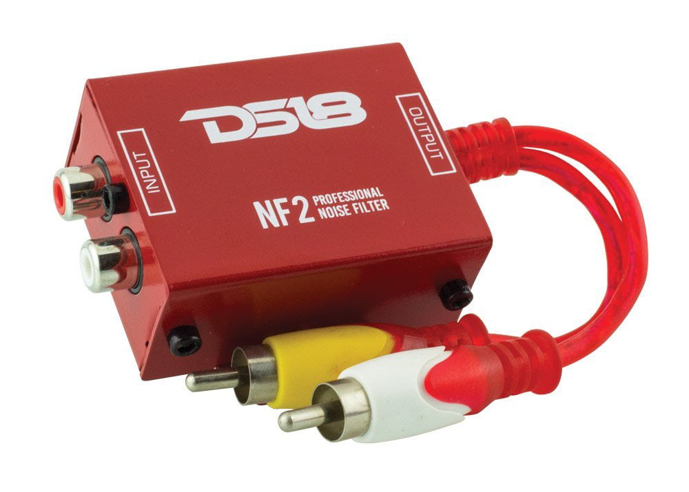
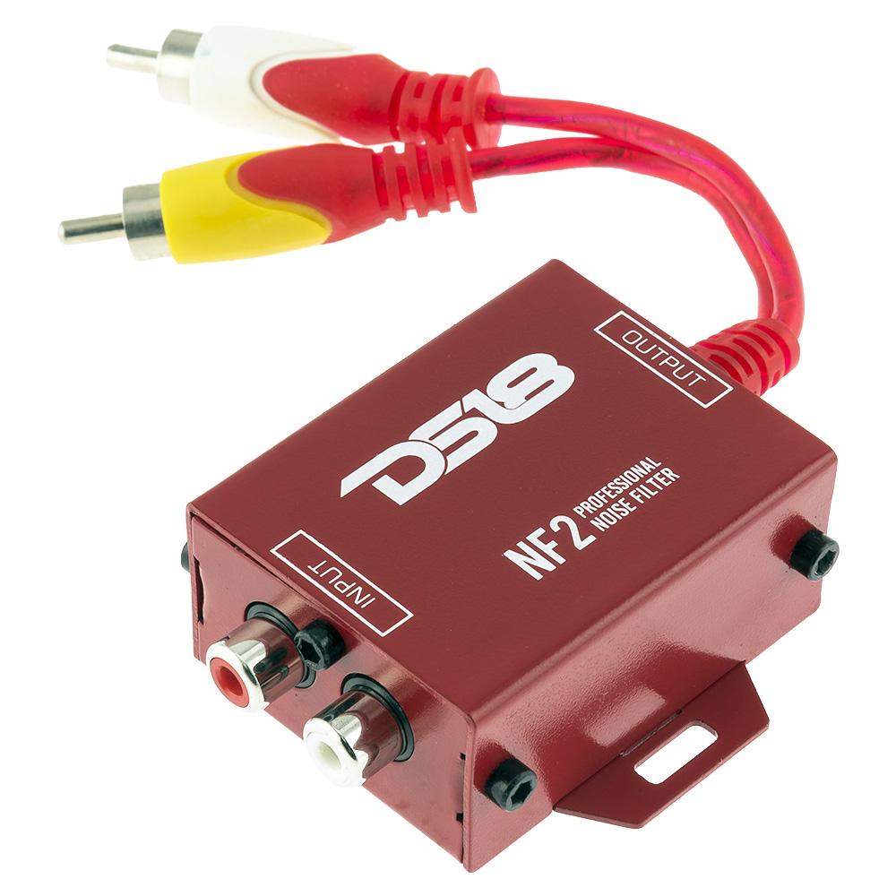
I intend to get another ground-loop isolator if that is what is required to fix remaining issues 2 and 4. I found 2 Nexxtech branded ground-loop isolators in my stash of parts and installed them on AWE64 and Audiotrix 3D/XG outputs, which completely eliminated the hum on those devices. Ĥ) When I isolate the input used by the component switcher on the DPS12 mixer, select the SC-88 and set a high volume on the DPS12's headphone out, I get ALMOST no discernible hum. ģ) When I isolate the input used by the component switcher on the DPS12 mixer, select the MT-32 and set a high volume on the DPS12's headphone out, I get no discernible hum. ġ) When I isolate either the AWE64 or Audiotrix 3D/XG on the DPS12 mixer and set a high volume on the DPS12's headphone out, I get humĢ) When I isolate the input used by the component switcher on the DPS12 mixer, select the Gravis Ultrasound and set a high volume on the DPS12's headphone out, I get hum. All midi modules are fed from the AWE64's midi port using a joystick MIDI adapter from the 90s and a MIDISPORT 2x4 in passive mode with one out looped-back to input to act as three output MIDI thru box. line outputs on all cards and modules and gain on DPs12 are roughly adjusted to similar volume levels, but below clipping level.

The MT-32, SC-88, MU500 and Gravis Ultrasound are connected to the component switcher, which in turn is connected to a dedicated stereo input on the DPS12. The AWE64 and Audiotrix 3D/XG are each connected directly to a dedicated stereo input on the DPS12 Other than b) there are no connections to other AC powered devices.

The DPS12's optical S/PDIF output is plugged into an AVR (hardly ever used).
#Ground loop isolator schematic Pc#
There is an Ethernet cable connected between the PC and and Ethernet switch (switch is on the same circuit, but different outlet). Everything is plugged into the same power bar (MIDI modules, DPS12, PC, monitor, OSSC, HDMI scaler, monitor, component input switcher) III.I have an Akai DPS12 that I use as a mixer and a retro PC (PC, monitor, OSSC, HDMI scaler) with multiple sound cards (AWE64 Audiotrix 3D/XG and Gravis Ultrasound) as well 3 MIDI modules (MT-32, SC-88 and MU500 ) and a component input switcher. Note: Since the power supply provided by the power distribution function of the control system input module (or input of instrument) is not isolated from the input terminal, the output signal of the power supply mode of the transmitter is common-grounded with power supply. Wiring diagram of loop powered isolator with input signal of 2-wire transmitter: Wiring diagram of loop powered isolator with input signal of 3-wire transmitter:ģ. Wiring diagram of loop powered isolator with input signal of 4-wire transmitter:Ģ. The wiring method of the external powered input module/instrumentġ. Wiring diagram of loop powered isolator with external powered 2-wire transmitter: Wiring diagram of loop powered isolator with external powered 3-wire transmitter:ģ. Note: This is a typical wiring diagram of a loop powered signal isolator (get energy from the input) and 4-wire transmitter, detailed parameters of loop powered signal isolator (ATO-S-SINIR-502E) are in the product page.Ģ. Wiring diagram of loop powered isolator with external powered 4-wire transmitter: The wiring method of the external powered transmitterġ. The following is seven wiring diagrams of the loop powered signal isolator and the various powered sensors and the different types of control system input module (or input of instrument). The use of loop powered signal isolators not only serves as signal isolation but also don't require an external power supply, which saves one-third of the wiring effort, and the cost of the power cable and the power supply. Using an external powered signal isolator (such as the ATO-S-SINIR-210E) in the control system requires the installation of isolators and external power supply that support the operation of the isolator in the control cabinet of the control system.

Loop powered signal isolators use the signal current in the input loop to power the meter (take out some energy of input signal inside the isolator to drive the isolator), without any external power supply. The function of the loop powered signal isolator is to isolate the current source signal input to the loop powered isolator and output a DC signal that is isolated from and proportional to the input signal. Loop powered signal isolator is one type of signal isolator with a power supply module.


 0 kommentar(er)
